Laser Technology Inc. (LTI) offers a full range of standard and custom industrialized shearography and holography solutions for nondestructive testing (NDT). Our instruments and systems are used to ensure quality and engineering compliance in composites manufacturing, i.e. boats and ships, aircraft and aircraft engines, turbine engines, spacecraft, missiles, launch vehicles, and rocket engines.
Shearography and holography are powerful tools for nondestructive testing each with its pros and cons. Both methods use lasers to illuminate the area on the test object for inspection and perform interferometric imaging. The images are formed using the interference of the laser light and show how the test object has deformed when subjected to a change in stress. These nanometer-sized transitory deformations can reveal the size and shape of otherwise hidden flaws. These laser methods are full field, able to inspect the entire area within the camera field-of-view (FOV) and do it fast. Ultrasonic holography for jet aircraft engine compressor seals takes less than 120 milliseconds, per image. Acoustic Shearography for inspecting bonded thermal protection system (TPS) foam on satellite launch vehicles can have a throughput of 1,500 sq. ft. per hour.
But for holography, the need to keep all the optical components and the test object in spatial registration to better than ¼ wavelength of the laser light means the test objects must fit onto a vibration isolation table. This requirement for stability imposes a limit of about 1M³ on the size of an object that can be readily inspected with holography.
Shearography on the other hand is a vibration-resistant optical system and when it was developed in 1986 proved to be a breakthrough allowing objects to be tested without the need for a vibration isolation table. Over the last 36 years well over a thousand portable shearography cameras, large scanning gantries, and robot systems have been implemented.
How Laser NDT Methods Work
Holography
In digital holography, the laser light is split into a reference beam that illuminates the CMOS camera directly and an illumination beam that is used to light up the test object. Laser light reflecting from the object is captured by the holographic camera lens and is mixed or interfered with the reference beam. The light then is directed to a CMOS sensor and streamed to the image processing computer. The camera, test part, and stressing equipment are all on a vibration isolation table.
Fig. 1 shows a holography system for inspecting turbine aircraft engine compressor seals. Similar systems are used for medical implant devices and hybrid semiconductor packages.
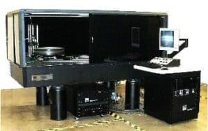
Fig. 2 and Fig. 3 below show a compressor stage with metallic braze bonded seals on three lands. The complex geometry makes ultrasonic testing (UT) inspection problematic. In holography, the test parts are clamped and excited with an ultrasonic signal. Material with underlying disbonds is more compliant and the vibration causes microscopic movement that appears black in the hologram. Interpretation and defect measurements are simple, and the acceptance criteria are the same as for UT.
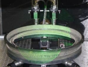
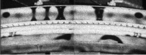
Fig. 4 below left shows a hemispherically shaped medical device the black areas are disbonds.
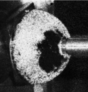
Fig. 5 below shows a holographic result for a HiRel hybrid semiconductor package with internal welded cavities tested for unbonds during the manufacturing process. With ultrasonic holography, bonded areas appear white, and disbonds are black along with the open cavities formed by the walls. This hybrid circuit package has multiple internal walls that should be welded to the package lid. Three welding defects are shown (white arrows) in this device, which measures about 3.2 inches in length.
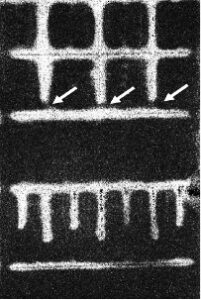
Fig. 6 Another hybrid semiconductor device is shown below along with its ultrasonic hologram. The photograph shows the pattern of the welds on the lid where the internal walls should be joined. In this case, most of the welded walls are disbonded. The white indications show where there is weld present.

Holography NDT has been highly effective for use with metal welded or braze bonded components, often with complex geometries. These parts conduct ultrasonic signals without significant attenuation providing excellent vibration resonance response and defect detection.
Applications include turbine aircraft engines, metallic bonds in medical orthopedic implants, and microwave semiconductor hybrid packages.
Shearography
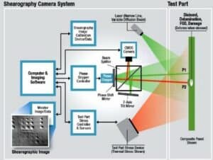
In digital shearography cameras, all the laser light is directed to lighting the test object. Laser light reflecting from the object is captured by a shearography camera lens and a beam splitter then divides the light into two equally intense images of the object. In a shearography camera, you can then adjust the lateral offset of one image with respect to the other or shear the images. The amount and direction of this image shearing are referred to as the Shear Vector (Sv) and is an important parameter for determining the defect sensitivity. This common-path interferometer does two things. First, it significantly reduces the effect of environmental motion and second, the generated shearograms show the first derivative of the test object deformation. This enhances defect indications and reduces sensitivity to test part deformation during thermal stressing. The two mixed images create an interferogram at the CMOS sensor. For both holography and shearography, the interferograms are streamed to an image processor and images captured before and after stressing are combined to create a real-time display of the object deformation and the final shearogram showing any flaw indications.
Fig. 7 shows a schematic diagram for a shearography camera.
Even though no vibration isolation table is needed, the camera and test parts need to stay in mechanical registration during the data acquisition, usually within 10e-3 inches, instead of fractions of a micron as required for holography. But the resistance of shearography to the image degrading effects of environmental vibration allows a wide range of cameras and parts scanning options. Shearography cameras come in handheld portable versions as well as cameras mounted on robots or large gantry scanners.
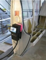
Portable shearography NDT instruments vacuum attach to the test surface, effectively locking the camera to the test part. The instrument then moves with the vehicle as it is rocked by the wind, waves (boats), and the presence of other workers. Portable shearography systems are especially useful for inspecting almost any type of composite vehicle including rail and monorail cars, motor and sailing yachts, racing boats, naval vessels, rescue boats, commercial and military aircraft, helicopters, launch vehicles, and spacecraft. Fig. 8, 9, and 10 below, show three examples.
Fig. 8 The LTI-5200 is shown being used for inspections of composite boat hull for damage, voids, and disbonds. This unit can do sequential vacuum and thermal stress shearography.
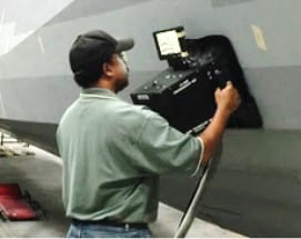
Fig. 9 The LTI-6200 is a portable thermal stress shearography system, perfect for inspecting for impact damage or delamination in composite materials.
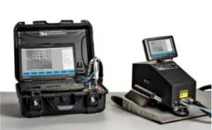
Fig. 10 The LTI-6200 is shown being used for inspection of composite rail car interior panels for damage and disbonds. A switch on the handle engages the vacuum pump to “vacuum lock” the camera to the test part surface. Portable systems have light shields allowing use in broad daylight, outdoor conditions.
Shearography cameras are frequently mounted on tripods or robots for use in testing laboratories or manufacturing facilities. The robot-mounted cameras can be combined with additional motion devices such as robot transport units (RTU) or fixtures to rotate the test part.
Fig. 11 The LTI-2100 is shown mounted on a tripod for use in an engineering test lab.
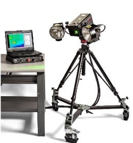
Fig. 12 The LTI-2100 mounted on a robot tool is used for a large composite section of a launch vehicle.
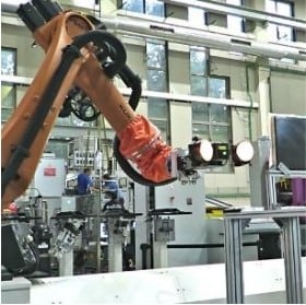
Fig. 13 An LTI-2100 was used for thermal shearography of a Kevlar panel to image and measure damage during ballistic tests. Four impact areas are seen in this shearography image.
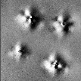
Fig. 14 An LTI-2100 using thermal stress imaged hundreds of microcracks in a concrete test block. Most of these cracks were smaller than detectable with an optical microscope.
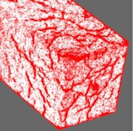
Fig. 15 shows a large two-camera dual gantry shearography system built inside a vacuum test chamber. Such shearography systems are highly effective for large aircraft radomes (shown below), aircraft control surfaces as well as helicopter blades
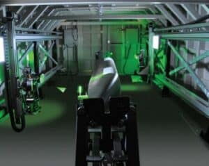
Fig.16 shows a large aircraft flap with more than 100 disbonds.
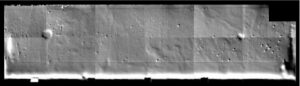
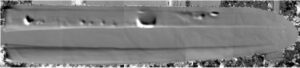
Fig. 17 is a vacuum shearography test result for a 65-inch composite propeller blade with a metal spar with a foam-filled composite shell. There are numerous internal voids detected.
Shearography NDT has been highly effective for use with both metal and composite parts and structures throughout several industries including space and aerospace, marine, automotive, and wind power. For larger test parts without very complex geometries the small double image created by the shearography camera does not pose a problem for image analysis and the relative insensitivity to motion has allowed users to combine shearography cameras with large scanning gantries and robots.
Both holography and shearography are powerful mature tools for nondestructive testing. LTI will work with you to select and develop the best NDT method to meet your requirements. Contact us to get started.