Shearography nondestructive testing has evolved considerably since first used on a production aircraft program in the USA in 1986. Shearography laser interferometric imaging methods measure test structure deformation due to an applied engineered change in stress. The resulting changes in Z-Axis strain component reveal images of subsurface defects such as disbonds, delaminations, core defects and impact damage in aerospace structures. Shearography NDT provides high thru-put, cost-effective productivity enhancements, improved manufacturing processes and quality inspection. Development of digital CCD cameras, the PC and small, high power solid-state lasers have led to dramatic performance improvements in shearography instruments and systems. Shearography is currently in use on a wide variety of aircraft including F-22, F-35 JSF, Airbus, Cessna Citation X, Raytheon Premier I and the NASA Space Shuttle.
This presentation will provide a brief background on shearography NDT technology as well as recent developments in production and portable on-aircraft shearography inspection technologies and applications.
Shearography Background
In today’s highly competitive aerospace environment, a capable high-speed inspection technology is critical. Shearography nondestructive testing is providing a better and faster means to nondestructively inspecting new aircraft both during manufacturing and in the field. In the quest to maximize fuel economy and performance, engineers have turned from riveted and bonded aluminum structures to solid composite materials, composite sandwich panels with honeycomb or foam cores and tape wound composite structures such as fuselages. The traditional methods for nondestructive testing, such as ultrasonic (UT) C-Scan, may not provide the best defect detection capability for these new materials and geometries and are slow with a typical through-put of just 10 sq. ft./hour. Further, the process of manufacturing complex composite structures requires a means for fast inspection to provide a process control feedback and to ensure quality and reliability at the lowest possible cost. In many aerospace programs today, laser shearography is providing a large part of the solution.
History of Shearography NDT
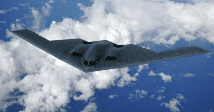
The electronic laser shearography imaging interferometer was pioneered in the early 1980’s by three researchers, Dr. John Butters at Loughborough University in the UK, Dr. S. Nakadate in Japan and Dr. Mike Hung at Oakland University in the USA. The author’s team at Laser Technology Inc. led the development of the shearography camera as a tool for nondestructive testing, delivering the world’s first production shearography NDT system to Northrop Grumman in 1987 for the manufacturing of the USAF B2 Stealth Bomber.
In the past twenty years more than 1,200 shearography systems have been integrated into the manufacturing process for aircraft composites, tires and high-reliability electronics. As with all NDT methods and technologies, shearography’s strengths and weakness must be completely understood, and applications qualified through Probability of Detection (PoD) verification with written procedures and rigorous training for operators and engineers alike. Once qualified, however, shearography systems can operate with extraordinary efficiency reaching through-puts from 25 to 1200 sq. ft per hour, 2.5 to 120 times the typical 10 sq. ft./hour inspection rate for ultrasonic C-Scan.
Shearography NDT
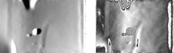
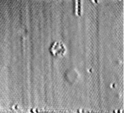
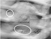
Unlike UT C-Scan, which uses a single transducer that requires a raster scan over the part to build up an image, Shearography is a whole field, real-time imaging technique that reveals out of-plane deformation derivatives in response to and applied stress. Using a slight pressure
reduction in a shearography test chamber, critical defects are imaged and measured in seconds. The shearography camera detects surface bumps as small as 3 nanometers caused by local strain changes around subsurface defects as the pressure is reduced on the test object. Vacuum shearography is highly effective for image disbonds, delaminations, core damage and core splice-joint separations in composite materials. Other Shearography NDT techniques that are frequently used include thermal pulse shearography for non-visible impact damage, pressure shearography for damage to composite wrapped pressure vessels. Vibration shearography has been highly developed in the last several years by the author to inspect the foam on the external tank of NASA’s Space Shuttle.
Portable Shearography NDT Instruments
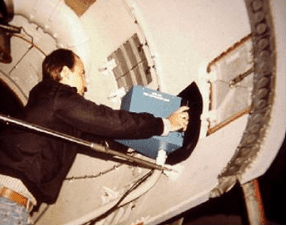
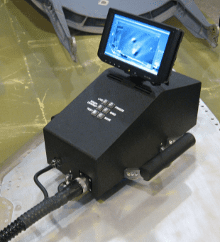
Portable shearography instruments that vacuum attach to an aircraft surface were developed by LTI in 1993. Combining a shearography stressing mechanism such as vacuum or thermal stress, with a vacuum attachment feature allows shearography to be performed in the field. These NDT instruments can be used on-aircraft, even on the tarmac or in a hangar environment and offer excellent inspection capability for a wide variety of defect types including non-visible impact damage, disbonds, voids, delaminations, water entrapment and porosity in composite repairs.
Production Shearography Systems
Composite aircraft manufacturing requires 100% inspection of all bonded surfaces to verify structural integrity and compliance with design. Traditional UT C-Scan generally uses water jets as a couplant for the ultrasonic signal. Honeycomb panels can absorb water requiring drying. The complete inspection cycle can take many hours or days to complete. Time is lost waiting for disposition of the test object. Shearography provides inspection results in minutes, without any test object contamination or wetting. Errors in processes can be corrected quickly before new parts are improperly made. Laser projection of the shearography defect indications onto the test object surface allows exact defect location and marking for repair. Introduced on the USAF B-2 production program, gantry mounted shearography systems share many operational features with UT C-scan systems. These include: teach/learn part scan programming, electronic image of the entire test object, image analysis and defect measurement tools, automated operation. Shearography system, however, operate at throughputs typically in the range of 100 to 500 sq. feet/hour compared to a typical throughput of 10 sq. ft./ hour for UT C-Scan systems. In addition, shearography gantries are considerably less expensive than comparable sized ultrasonic C-Scan systems since precision part contour following is unnecessary. Currently dozens of these systems are in operation on aerospace manufacturing programs.
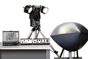
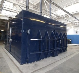
Photo 9 Shearography is used extensively during the manufacturing of aircraft (left). Test objects such as the radome, slats, flaps, panels and control surfaces are inspected with the LTI-9000 Shearography system using vacuum stress. The dual test chamber shearography system (left) allows test objects up to 10 m. in length to be inspected. Inside the test shearography (right) are chamber gantries to provide complete automatic coverage of the test object.
Conclusions
Shearography is a mature and cost effective NDT technology for many aerospace applications. Shearography provides very rapid inspection allowing immediate feedback for process controls as well as field inspection capability. Recent inclusion in ASNT TC-1A will help further the development of new applications and methods.
Contact Laser Technology Inc. to see how we can help your program.